Driver Interface
- Arm Driver Interface: Used for arm control and state feedback.
- Torso Driver Interface: Used for torso control and state feedback.
- Chassis Driver Interface: Used for chassis state feedback.
- Camera Interface: Used for camera state feedback.
- IMU Interface: Used for IMU state feedback.
- BMS Interface: Used for BMS battery state feedback.
- Remote Controller Interface: Used for torso and chassis remote controller state feedback.
Arm Driver Interface
This interface is a ROS package for arm control and state feedback. It defines multiple topics for publishing and subscribing to arm states, control commands, and related error codes. The following is a detailed description of each topic and its corresponding message type:
| Topic Name | I/O | Description | Message Type |
|---|---|---|---|
| /hdas/feedback_arm_left | Output | Left arm joint feedback | sensor_msgs::msg::JointState |
| /hdas/feedback_arm_right | Output | Right arm joint feedback | sensor_msgs::msg::JointState |
| /hdas/feedback_gripper_left | Output | Left gripper travel | sensor_msgs::msg::JointState |
| /hdas/feedback_gripper_right | Output | Right gripper travel | sensor_msgs::msg::JointState |
| /hdas/feedback_status_arm_left | Output | Left arm state feedback | hdas_msg::msg::FeedbackStatus |
| /hdas/feedback_status_arm_right | Output | Right arm state feedback | hdas_msg::msg::FeedbackStatus |
| /motion_control/control_arm_left | Input | Left arm motor control | hdas_msg::msg::MotorControl |
| /motion_control/control_arm_right | Input | Right arm motor control | hdas_msg::msg::MotorControl |
| /motion_control/control_gripper_left | Input | Left gripper motor control | hdas_msg::msg::MotorControl |
| /motion_control/control_gripper_right | Input | Right gripper motor control | hdas_msg::msg::MotorControl |
The specific fields of the topics above and their detailed descriptions are shown in the table below:
| Topic Name | Field | Description |
|---|---|---|
| /hdas/feedback_arm_left | header | Standard message header |
| position | [Joint 1 position, Joint 2 position, Joint 3 position, Joint 4 position, Joint 5 position, Joint 6 position, gripper joint position] | |
| velocity | [Joint 1 velocity, Joint 2 velocity, Joint 3 velocity, Joint 4 velocity, Joint 5 velocity, Joint 6 velocity, gripper joint velocity] | |
| effort | [Joint 1 torque, Joint 2 torque, Joint 3 torque, Joint 4 torque, Joint 5 torque, Joint 6 torque, gripper joint torque] | |
| /hdas/feedback_arm_right | header | Standard message header |
| position | [Joint 1 position, Joint 2 position, Joint 3 position, Joint 4 position, Joint 5 position, Joint 6 position, gripper joint position] | |
| velocity | [Joint 1 velocity, Joint 2 velocity, Joint 3 velocity, Joint 4 velocity, Joint 5 velocity, Joint 6 velocity, gripper joint velocity] | |
| effort | [Joint 1 torque, Joint 2 torque, Joint 3 torque, Joint 4 torque, Joint 5 torque, Joint 6 torque, gripper joint torque] | |
| /hdas/feedback_gripper_left | header | Standard message header |
| position | Gripper travel (0-100mm) | |
| velocity | Not used for now | |
| effort | Not used for now | |
| /hdas/feedback_gripper_right | header | Standard message header |
| position | Gripper travel (0-100mm) | |
| velocity | Not used for now | |
| effort | Not used for now | |
| /hdas/feedback_status_arm_left | header | Standard message header |
| name_id | Joint names | |
| errors | Contains error codes and their corresponding error descriptions | |
| /hdas/feedback_status_arm_right | header | Standard message header |
| name_id | Joint names | |
| errors | Contains error codes and their corresponding error descriptions | |
| /motion_control/control_arm_left (MIT) |
header | Standard message header |
| name | - | |
| p_des | [Joint 1 position, Joint 2 position, Joint 3 position, Joint 4 position, Joint 5 position, Joint 6 position, gripper joint position] | |
| v_des | [Joint 1 velocity, Joint 2 velocity, Joint 3 velocity, Joint 4 velocity, Joint 5 velocity, Joint 6 velocity, gripper joint velocity] | |
| kp | [Joint 1 kp, Joint 2 kp, Joint 3 kp, Joint 4 kp, Joint 5 kp, Joint 6 kp, gripper joint kp] | |
| kd | [Joint 1 kd, Joint 2 kd, Joint 3 kd, Joint 4 kd, Joint 5 kd, Joint 6 kd, gripper joint kd] | |
| t_ff | [Joint 1 torque, Joint 2 torque, Joint 3 torque, Joint 4 torque, Joint 5 torque, Joint 6 torque, gripper joint torque] | |
| mode | - | |
| /motion_control/control_arm_left (PID) |
header | Standard message header |
| name | - | |
| p_des | [Joint 1 position, Joint 2 position, Joint 3 position, Joint 4 position, Joint 5 position, Joint 6 position, gripper joint position] | |
| v_des | - | |
| t_ff | - | |
| mode | - | |
| /motion_control/control_arm_right (MIT) |
header | Standard message header |
| name | - | |
| p_des | [Joint 1 position, Joint 2 position, Joint 3 position, Joint 4 position, Joint 5 position, Joint 6 position, gripper joint position] | |
| v_des | [Joint 1 velocity, Joint 2 velocity, Joint 3 velocity, Joint 4 velocity, Joint 5 velocity, Joint 6 velocity, gripper joint velocity] | |
| kp | [Joint 1 kp, Joint 2 kp, Joint 3 kp, Joint 4 kp, Joint 5 kp, Joint 6 kp, gripper joint kp] | |
| kd | [Joint 1 kd, Joint 2 kd, Joint 3 kd, Joint 4 kd, Joint 5 kd, Joint 6 kd, gripper joint kd] | |
| t_ff | [Joint 1 torque, Joint 2 torque, Joint 3 torque, Joint 4 torque, Joint 5 torque, Joint 6 torque, gripper joint torque] | |
| mode | - | |
| /motion_control/control_arm_right (PID) |
header | Standard message header |
| name | - | |
| p_des | [Joint 1 position, Joint 2 position, Joint 3 position, Joint 4 position, Joint 5 position, Joint 6 position, gripper joint position] | |
| v_des | [Joint 1 max velocity, Joint 2 max velocity, Joint 3 max velocity, Joint 4 max velocity, Joint 5 max velocity, Joint 6 max velocity, gripper joint max velocity] | |
| t_ff | [Joint 1 max torque, Joint 2 max torque, Joint 3 max torque, Joint 4 max torque, Joint 5 max torque, Joint 6 max torque, gripper joint max torque] | |
| mode | - | |
| /motion_control/control_gripper_left | header | Standard message header |
| name | - | |
| p_des | Gripper motor position | |
| v_des | Gripper motor velocity | |
| kp | Gripper motor kp | |
| kd | Gripper motor kd | |
| t_ff | Gripper torque | |
| mode | - | |
| /motion_control/control_gripper_right | header | Standard message header |
| name | - | |
| p_des | Gripper motor position | |
| v_des | Gripper motor velocity | |
| kp | Gripper motor kp | |
| kd | Gripper motor kd | |
| t_ff | Gripper torque | |
| mode | - |
Arm Joint Motor Control Interface
/motion_control/control_arm_left
/motion_control/control_arm_right
MIT Force-Position Hybrid Control Mode Architecture
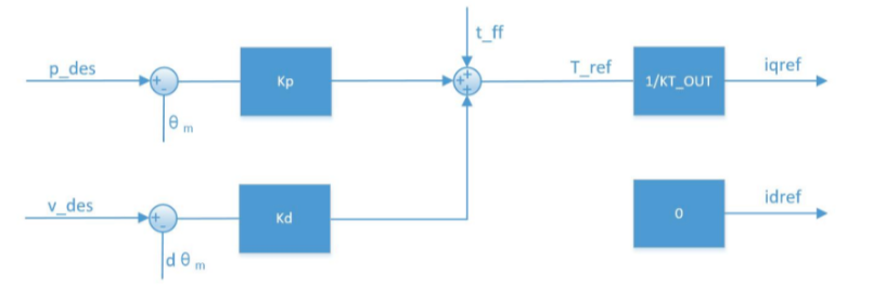
The motor output torque formula is used to compute the torque value Tref tracked by the current loop, as follows:
$K_p(p_d - p_e) + K_d(v_d - v_e)+t_{ff} = T_{ref}$
Where:
Kp and Kd are the proportional terms for position gain and velocity gain;
p_des and v_des are the desired position and velocity;
t_ff is the feedforward torque;
p_e is the position fed back by the encoder, and v_e is the motor speed obtained by differentiation.
- The input terms include:
Kp,Kd,pd,vd,t_ff. The feedback termspeandvedo not need to be entered manually.
Tips:
-
Feedforward torque: This value is mandatory. Since the position and velocity terms cannot compensate for large torque errors, the feedforward torque should at least compensate for the effect of the arm's own gravity.
-
Recommended gain settings: The following are the recommended
kpandkdvalues for the A1X motor. Please adjust them with caution.A1X_kp = [ 140.0, 200.0, 120.0, 80.0, 80.0, 80.0 ]
A1X_kd = [ 10.0, 30.0, 5.0, 10.0, 10.0, 10.0 ]
PID Servo Control Mode Architecture
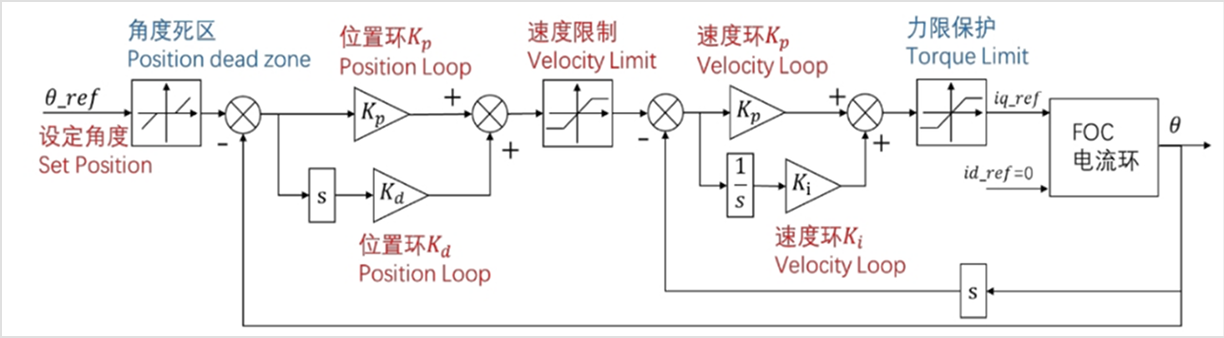
The servo control mode uses three-loop PID (position loop, velocity loop, current loop) control. This mode introduces an integral term and has a small steady-state error. To maintain interface consistency, its control data format is identical to that of the MIT interface.
Where:
p_des: the target angle (rad);
v_des: not meaningful;
k_p, k_d: not meaningful;
t_ff: not meaningful.
Torso Driver Interface
This interface is a ROS package for torso control and state feedback. It defines multiple topics for publishing and subscribing to the state and control commands of the torso motors. The following is a detailed description of each topic and its corresponding message type:
| Topic Name | I/O | Description | Message Type |
|---|---|---|---|
| /hdas/feedback_torso | Output | Torso joint feedback | sensor_msgs::msg::JointState |
| /hdas/feedback_status_torso | Output | Torso state feedback | hdas_msg::msg::FeedbackStatus |
| /motion_control/control_torso (this topic cannot actively publish messages) | Input | Torso motor control | hdas_msg::msg::MotorControl |
The specific fields of the topics above and their detailed descriptions are shown in the table below:
| Topic Name | Field | Description |
|---|---|---|
| /hdas/feedback_torso | header | Standard message header |
| position | [Joint 1 position, Joint 2 position, Joint 3 position, 0] | |
| velocity | [Joint 1 velocity, Joint 2 velocity, Joint 3 velocity, 0] | |
| effort | [Joint 1 torque, Joint 2 torque, Joint 3 torque, 0] | |
| /hdas/feedback_status_torso | header | Standard message header |
| name_id | Joint names | |
| errors | Contains error codes and their corresponding error descriptions | |
| /motion_control/control_torso | header | Standard message header |
| name | - | |
| p_des | [Joint 1 position, Joint 2 position, Joint 3 position, 0] | |
| v_des | [Joint 1 max velocity, Joint 2 max velocity, Joint 3 max velocity, 0] | |
| kp | [-, -, -, -] | |
| kd | [-, -, -, -] | |
| t_ff | [-, -, -, -] | |
| mode | - |
Chassis Driver Interface
This interface is a ROS package for chassis state feedback. It defines multiple topics to report the state of the chassis motors. The following is a detailed description of each topic and its associated message type:
| Topic Name | I/O | Description | Message Type |
|---|---|---|---|
| /hdas/feedback_chassis | Output | Chassis hub and steering motor feedback | sensor_msgs::msg::JointState |
| /hdas/feedback_status_chassis | Output | Chassis state feedback | hdas_msg::msg::FeedbackStatus |
| /motion_control/control_chassis | Input | Chassis hub and steering motor control | hdas_msg::msg::MotorControl |
The specific fields of the topics above and their detailed descriptions are shown in the table below:
| Topic Name | Field | Description |
|---|---|---|
| /hdas/feedback_chassis | header | Standard message header |
| position | [front-left wheel angle, front-right wheel angle, rear wheel angle] | |
| velocity | [front-left wheel linear velocity, front-right wheel linear velocity, rear wheel linear velocity] [front-left wheel angular velocity, front-right wheel angular velocity, rear wheel angular velocity] |
|
| effort | [0.0, 0.0, 0.0, 0.0, 0.0, 0.0] | |
| /hdas/feedback_status_chassis | header | Standard message header |
| name_id | Joint names | |
| errors | Contains error codes and their corresponding error descriptions | |
| /motion_control/control_chassis | header | Standard message header |
| name | - | |
| p_des | [front-left wheel angle, front-right wheel angle, rear wheel angle] | |
| v_des | [front-left wheel linear velocity, front-right wheel linear velocity, rear wheel linear velocity] | |
| kp | - | |
| kd | - | |
| t_ff | - | |
| mode | - |
Camera Interface
| Topic Name | I/O | Description | Message Type |
|---|---|---|---|
| /hdas/camera_wrist_left/color/image_raw/compressed | Output | Left wrist camera RGB compressed image | sensor_msgs::msg::CompressedImage |
| /hdas/camera_wrist_right/color/image_raw/compressed | Output | Right wrist camera RGB compressed image | sensor_msgs::msg::CompressedImage |
| /hdas/camera_head/left_raw/image_raw_color/compressed | Output | Head camera left-eye RGB compressed image | sensor_msgs::msg::CompressedImage |
| /hdas/camera_head/right_raw/image_raw_color/compressed | Output | Head camera right-eye RGB compressed image | sensor_msgs::msg::CompressedImage |
| /hdas/camera_wrist_left/aligned_depth_to_color/image_raw | Output | Left wrist camera depth image | sensor_msgs::msg::Image |
| /hdas/camera_wrist_right/aligned_depth_to_color/image_raw | Output | Right wrist camera depth image | sensor_msgs::msg::Image |
The specific fields of the topics above and their detailed descriptions are shown in the table below:
| Topic Name | Field | Description |
|---|---|---|
| /hdas/camera_wrist_left/color/image_raw/compressed | header | Standard message header |
| format | JPEG | |
| data | Image data | |
| /hdas/camera_wrist_right/color/image_raw/compressed | header | Standard message header |
| format | JPEG | |
| data | Image data | |
| /hdas/camera_head/left_raw/image_raw_color/compressed | header | Standard message header |
| format | JPEG format | |
| data | Image data | |
| /hdas/camera_head/right_raw/image_raw_color/compressed | header | Standard message header |
| format | JPEG format | |
| data | Image data | |
| /hdas/camera_wrist_left/aligned_depth_to_color/image_raw | header | Standard message header |
| height | Depends on the settings | |
| width | Depends on the settings | |
| encoding | 16UC1 | |
| is_bigendian | 0 | |
| step | Depends on the settings | |
| data | Image data | |
| /hdas/camera_wrist_right/aligned_depth_to_color/image_raw | header | Standard message header |
| height | Depends on the settings | |
| width | Depends on the settings | |
| encoding | 16UC1 | |
| is_bigendian | 0 | |
| step | Determined by the configuration | |
| data | Image data |
IMU Interface
| Topic Name | I/O | Description | Message Type |
|---|---|---|---|
| /hdas/imu_chassis | Output | Chassis IMU feedback | sensor_msgs::msg::Imu |
| /hdas/imu_torso | Output | Torso IMU feedback | sensor_msgs::msg::Imu |
The specific fields of the topics above and their detailed descriptions are shown in the table below:
| Topic Name | Field | Description |
|---|---|---|
| /hdas/imu_chassis | header | Standard message header |
| orientation.x | Quaternion x | |
| orientation.y | Quaternion y | |
| orientation.z | Quaternion z | |
| orientation.w | Quaternion w | |
| angular_velocity.x | Gyroscope angular velocity x | |
| angular_velocity.y | Gyroscope angular velocity y | |
| angular_velocity.z | Gyroscope angular velocity z | |
| linear_acceleration.x | Linear acceleration x | |
| linear_acceleration.y | Linear acceleration y | |
| linear_acceleration.z | Linear acceleration z | |
| /hdas/imu_torso | header | Standard message header |
| orientation.x | Quaternion x | |
| orientation.y | Quaternion y | |
| orientation.z | Quaternion z | |
| orientation.w | Quaternion w | |
| angular_velocity.x | Gyroscope angular velocity x | |
| angular_velocity.y | Gyroscope angular velocity y | |
| angular_velocity.z | Gyroscope angular velocity z | |
| linear_acceleration.x | Linear acceleration x | |
| linear_acceleration.y | Linear acceleration y | |
| linear_acceleration.z | Linear acceleration z |
BMS Interface
| Topic Name | I/O | Description | Message Type |
|---|---|---|---|
| /hdas/bms | Output | Battery BMS message | hdas_msg::msg::Bms |
The specific fields of the topics above and their detailed descriptions are shown in the table below:
| Topic Name | Field | Description |
|---|---|---|
| /hdas/bms | header | Standard message header |
| voltage | Voltage (V) | |
| current | Current (I) | |
| capital | Remaining battery (%) |
Remote Controller Interface
| Topic Name | I/O | Description | Message Type |
|---|---|---|---|
| /controller | Output | Remote controller signal | hdas_msg::msg::ControllerSignalStamped |
The specific fields of the topics above and their detailed descriptions are shown in the table below:
| Topic Name | Field | Description |
|---|---|---|
| /controller | header | Standard message header |
| data.left_x_axis | Left joystick x direction | |
| data.left_y_axis | Left joystick y direction | |
| data.right_x_axis | Right joystick x direction | |
| data.right_y_axis | Right joystick y direction | |
| mode | 2: remote controller control (chassis) 5: host computer control (chassis) |
    <tr style="text-align: left;">
        <td style="padding: 8px; border: 1px solid #ddd;" rowspan="11">/hdas/imu_torso</td>
        <td style="padding: 8px; border: 1px solid #ddd;">header</td>
        <td style="padding: 8px; border: 1px solid #ddd;">Standard message header</td>
    </tr>
    <tr style="text-align: left;">
        <td style="padding: 8px; border: 1px solid #ddd;">orientation.x</td>
        <td style="padding: 8px; border: 1px solid #ddd;">Quaternion x</td>
    </tr>
    <tr style="text-align: left;">
        <td style="padding: 8px; border: 1px solid #ddd;">orientation.y</td>
        <td style="padding: 8px; border: 1px solid #ddd;">Quaternion y</td>
    </tr>
    <tr style="text-align: left;">
        <td style="padding: 8px; border: 1px solid #ddd;">orientation.z</td>
        <td style="padding: 8px; border: 1px solid #ddd;">Quaternion z</td>
    </tr>
    <tr style="text-align: left;">
        <td style="padding: 8px; border: 1px solid #ddd;">orientation.w</td>
        <td style="padding: 8px; border: 1px solid #ddd;">Quaternion w</td>
    </tr>
    <tr style="text-align: left;">
        <td style="padding: 8px; border: 1px solid #ddd;">angular_velocity.x</td>
        <td style="padding: 8px; border: 1px solid #ddd;">Gyroscope angular velocity x</td>
    </tr>
    <tr style="text-align: left;">
        <td style="padding: 8px; border: 1px solid #ddd;">angular_velocity.y</td>
        <td style="padding: 8px; border: 1px solid #ddd;">Gyroscope angular velocity y</td>
    </tr>
    <tr style="text-align: left;">
        <td style="padding: 8px; border: 1px solid #ddd;">angular_velocity.z</td>
        <td style="padding: 8px; border: 1px solid #ddd;">Gyroscope angular velocity z</td>
    </tr>
    <tr style="text-align: left;">
        <td style="padding: 8px; border: 1px solid #ddd;">linear_acceleration.x</td>
        <td style="padding: 8px; border: 1px solid #ddd;">Linear acceleration x</td>
    </tr>
    <tr style="text-align: left;">
        <td style="padding: 8px; border: 1px solid #ddd;">linear_acceleration.y</td>
        <td style="padding: 8px; border: 1px solid #ddd;">Linear acceleration y</td>
    </tr>
    <tr style="text-align: left;">
        <td style="padding: 8px; border: 1px solid #ddd;">linear_acceleration.z</td>
        <td style="padding: 8px; border: 1px solid #ddd;">Linear acceleration z</td>
    </tr>
</tbody>
BMS Interface
| Topic Name | I/O | Description | Message Type |
|---|---|---|---|
| /hdas/bms | Output | Battery BMS message | hdas_msg::bms |
The specific fields of the topics above and their detailed descriptions are shown in the table below:
| Topic Name | Field | Description |
|---|---|---|
| /hdas/bms | header | Standard message header |
| voltage | Voltage (V) | |
| current | Current (I) | |
| capital | Remaining battery (%) |
Remote Controller Interface
| Topic Name | I/O | Description | Message Type |
|---|---|---|---|
| /controller | Output | Remote controller signal | hdas_msg::controller_signal_stamped |
The specific fields of the topics above and their detailed descriptions are shown in the table below:
| Topic Name | Field | Description |
|---|---|---|
| /controller | header | Standard message header |
| data.left_x_axis | Left joystick x direction | |
| data.left_y_axis | Left joystick y direction | |
| data.right_x_axis | Right joystick x direction | |
| data.right_y_axis | Right joystick y direction | |
| mode | 2: remote controller control (chassis) 5: host computer control (chassis) |