Unboxing Guide
1. Check the Packing List
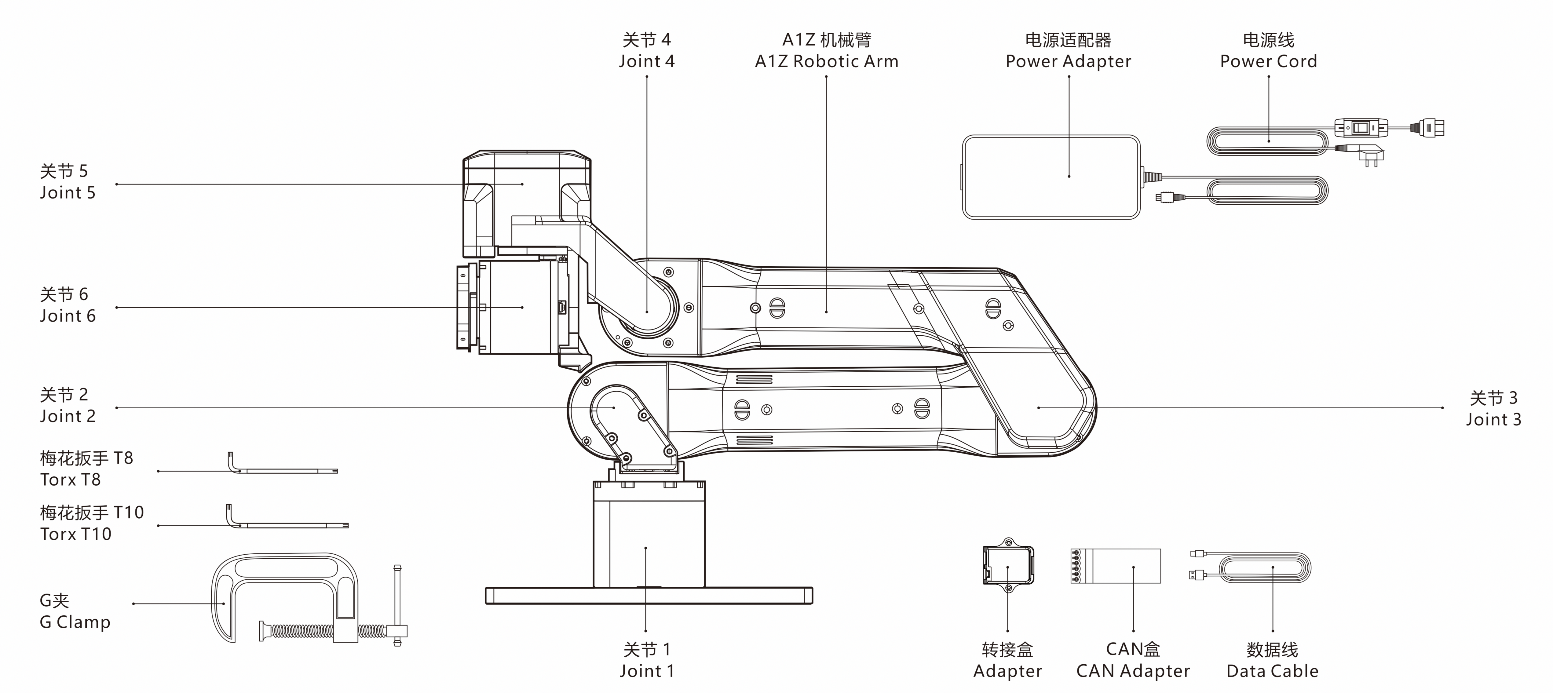
After opening the package, check the following items carefully against the shipping list:
 A1Z packing list illustration
| Item | Quantity | Notes |
|---|---|---|
| A1Z robotic arm | 1 | Robotic arm body |
| Power adapter | 1 | 24V@15A. The AC cable is available in China-standard/US-standard versions and includes a circuit switch button. |
| CAN box and accessories (USB cable, screwdriver, CAN signal cable) | 1 | Used for robotic arm communication. |
| Adapter box | 1 | Connects the robotic arm, communication terminal, and power terminal. |
| G-clamp | 2 | G-shaped fasteners used to fix the mounting plate to the table. |
| Torx wrench | 2 | Used to fasten screws. |
| A1Z product manual | 1 | Introduces A1Z product details. |
| A1Z shipping list | 1 | Used to check delivered items. |
<span style={{ color: 'blue' }}>Note: The A1Z robotic arm does not include a gripper by default. Please contact us if you need to purchase one.
In addition, prepare the following item:
| Item | Quantity | Notes |
|---|---|---|
| Host computer | 1 | Control: Python >= 3.10 |
Note: To ensure normal product operation, place A1Z in a dry, well-ventilated environment with no obstacles or hazardous objects nearby.
2. Install the Arm Body
 Use G-clamps to fix the robotic arm to a stable tabletop
- Select a suitable mounting platform. Ensure the platform is flat, stable, and capable of bearing the maximum load during operation.
- Clean the mounting surface and remove debris, dust, or other materials that may affect installation stability. Ensure close contact between the mounting base plate and the platform.
Install and secure the robotic arm as follows:
- Place the G-clamp adapter plate on the selected platform or tabletop and ensure it is positioned properly for fastening.
- Secure the adapter plate with the G-clamps.
3. Connect the Cables
 A1Z connection diagram
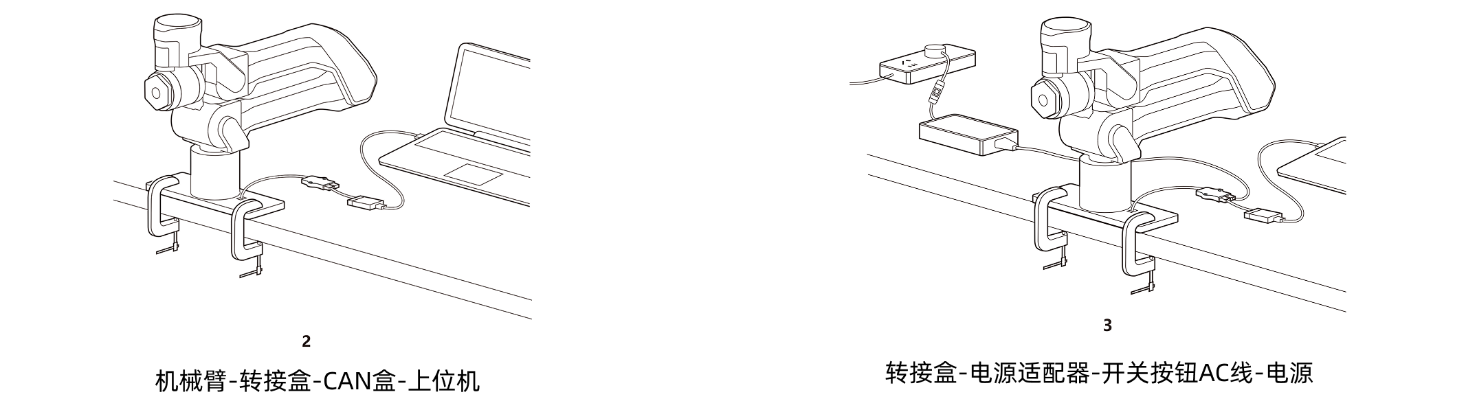
Connect the cables as follows:
- Communication: connect the cable attached to the robotic arm to the adapter box, connect the cable attached to the CAN box to the adapter box, and connect the USB cable between the CAN box and the host computer.
- Power: connect the cable attached to the power adapter to the adapter box, and connect the switched AC cable between the power adapter and the power source.
 A1Z CAN box diagram
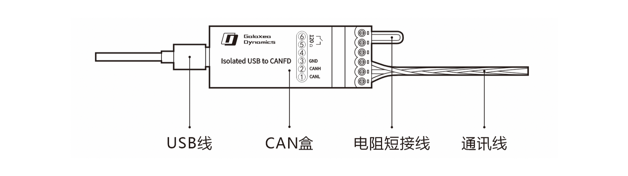
The original shorting wire connects a 120Ω termination resistor between pins ⑤ and ⑥ shown in the diagram, adding CAN termination to the CAN bus.
Note: If the original shorting wire is removed, connect one 120Ω termination resistor in parallel at each far end of the bus to ensure stable CAN communication.