About A1X
Safety Instructions
The Galaxea robotic arm may pose safety hazards if operated improperly.
- Before you start using the robotic arm, be sure to read the following safety notes in detail.
- Personnel who are not yet familiar with this safety guide must be strictly supervised when near the robot and must be clearly informed of the potential risks of robot operation.
- Before using this product, be sure to thoroughly inspect the surrounding environment to rule out any potential safety threats.
Technical Specifications
| Mechanical Parameter | A1X Value |
|---|---|
| Dimensions | 600L x 100W x 305H mm |
| Weight | 4.2 kg |
| Rated Voltage | 24V |
| Rated Current | 5A |
| Maximum Current | 8A |
| Communication Interface | USB2.0, CAN |
| Performance Parameter | A1X Value |
|---|---|
| Degrees of Freedom | 6 |
| Rated Payload | 3kg@0.6m |
| Maximum Payload | 5kg@0.6m |
| Arm Reach | 600 mm |
| Maximum End-Effector Linear Velocity | 5 m/s |
| Maximum End-Effector Acceleration | 38 m/s² |
| Repeatability | ±0.05 mm |
Hardware Architecture
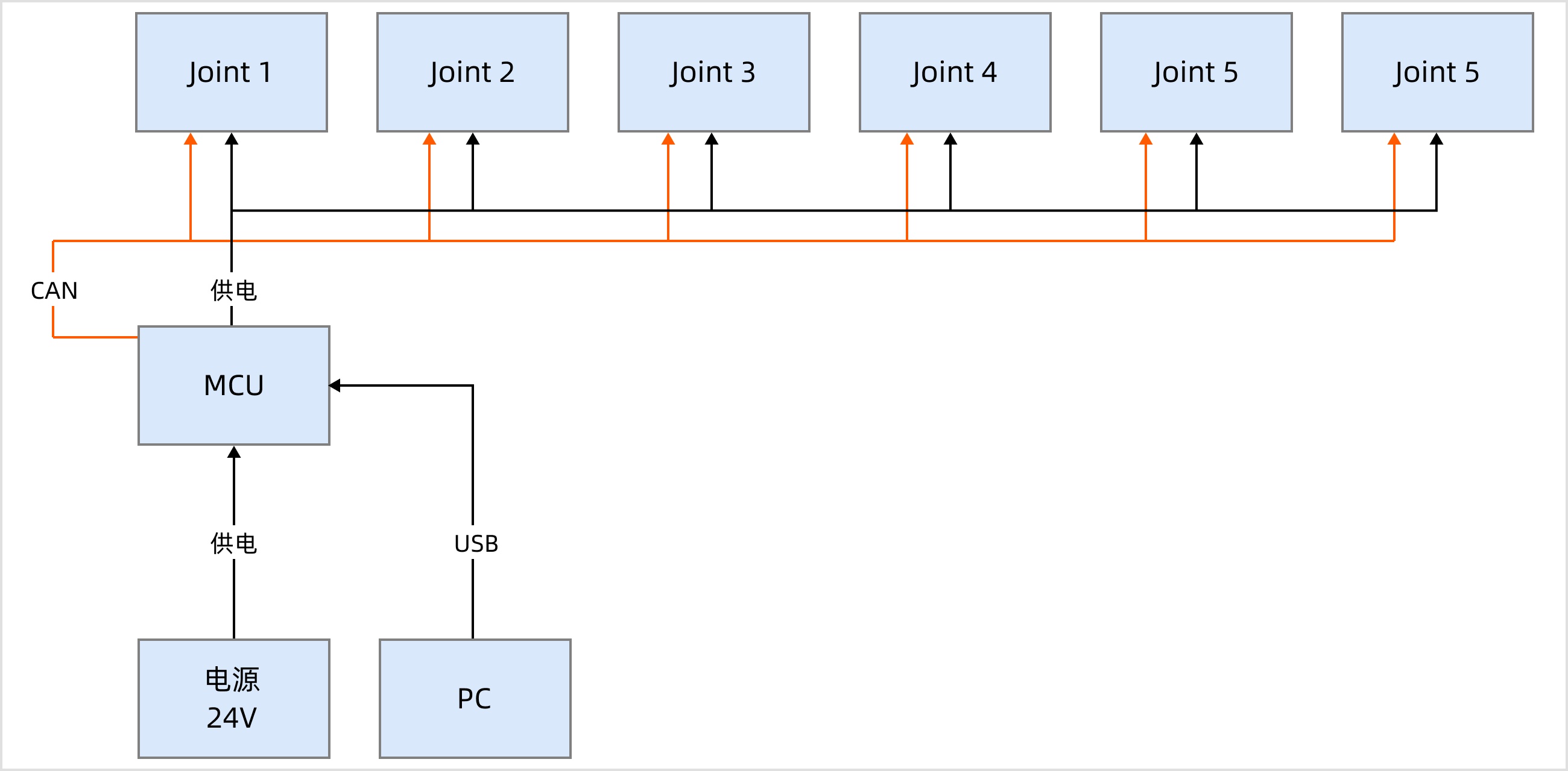
Mechanical Structure
Joints
A1X
The A1X robotic arm has 6 joints, with a maximum rotation angle of 330 degrees.
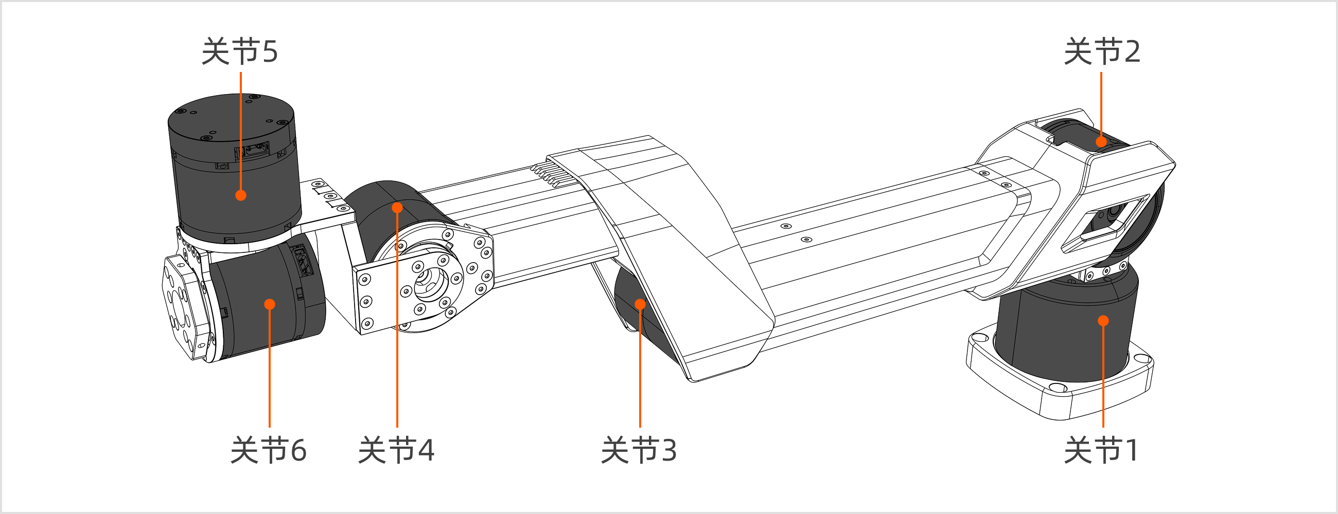
| Joint | Rated Torque (Nm) | Peak Torque (Nm) | Rated Speed (rpm) | Peak Speed (rpm) | Gear Ratio | Working Range |
|---|---|---|---|---|---|---|
| Joint 1 | 9 | 27 | 36 | 100 | 40 | [-165°,165°] |
| Joint 2 | 20 | 50 | 40 | 120 | 39 | [0, 180°] |
| Joint 3 | 9 | 27 | 36 | 100 | 40 | [-190°,0°] |
| Joint 4 | 5 | 12 | 260 | 315 | 10 | [-90°,90°] |
| Joint 5 | 5 | 12 | 260 | 315 | 10 | [-90°,90°] |
| Joint 6 | 5 | 12 | 260 | 315 | 10 | [-165°, 165°] |
Note: Each joint of the robotic arm has a 2° limit protection on its working range.
The working range of each joint of the robotic arm is shown in the figure below:
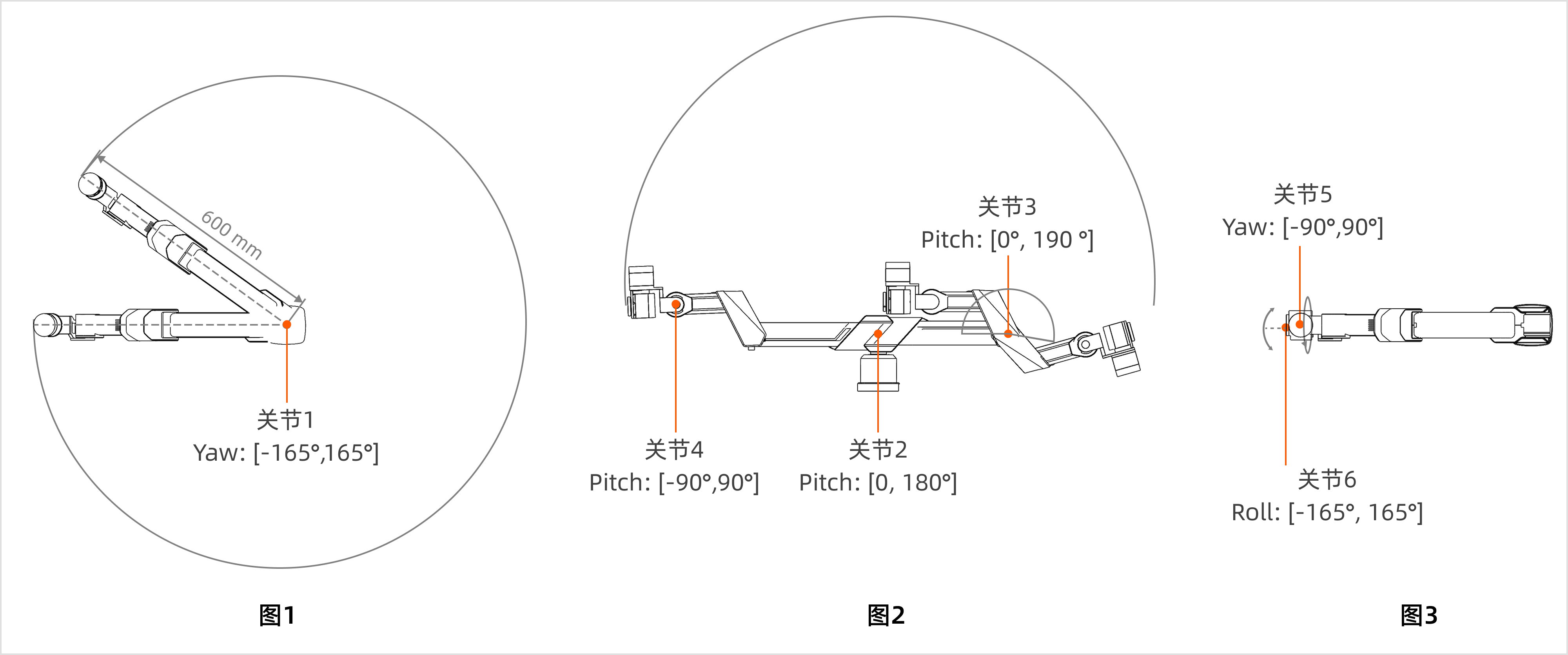
- Figure 1: The maximum rotation angle of Joint 1 in the Yaw direction is 330 degrees, with a rotation radius of 600 mm.
- Figure 2: The maximum rotation angles of Joint 2 and Joint 3 in the positive Pitch direction are 180 degrees and 190 degrees respectively; the maximum rotation angle of Joint 4 in the Pitch direction is 180 degrees.
- Figure 3: The maximum rotation angle of Joint 5 in the Yaw direction is 180 degrees; the maximum rotation angle of Joint 6 in the Roll direction is 330 degrees.
Base
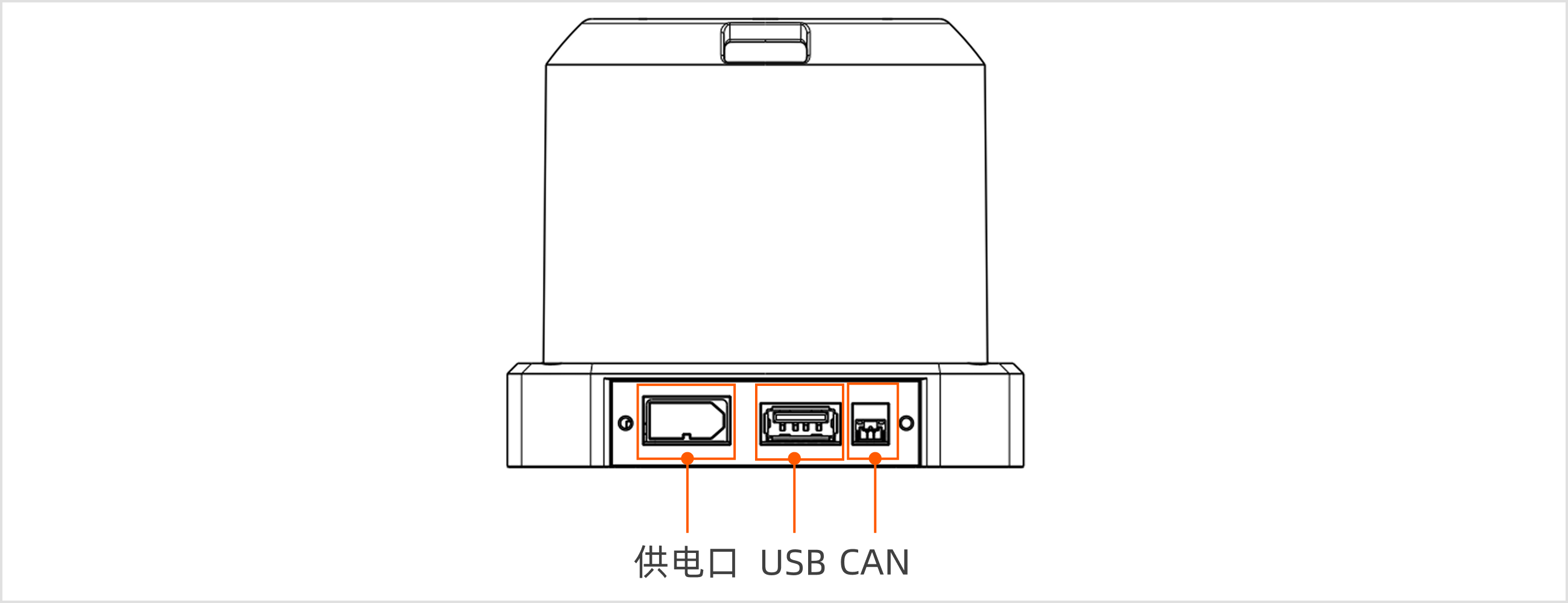
| Base | Remarks |
|---|---|
| Dimensions | 75L x 75W mm |
| Power Port | Rated Voltage: 24 V |
| Communication Port | USB 2.0, CAN |
| Mounting Holes | Four M6 threads, 6.3 mm diameter |
End-Effector
Galaxea G1 Gripper
The Galaxea G1 is a self-developed parallel gripper, equipped with one joint motor and a two-finger clamp.
Note: The A1XY robotic arm does not include a gripper. Please contact us to purchase one if needed.
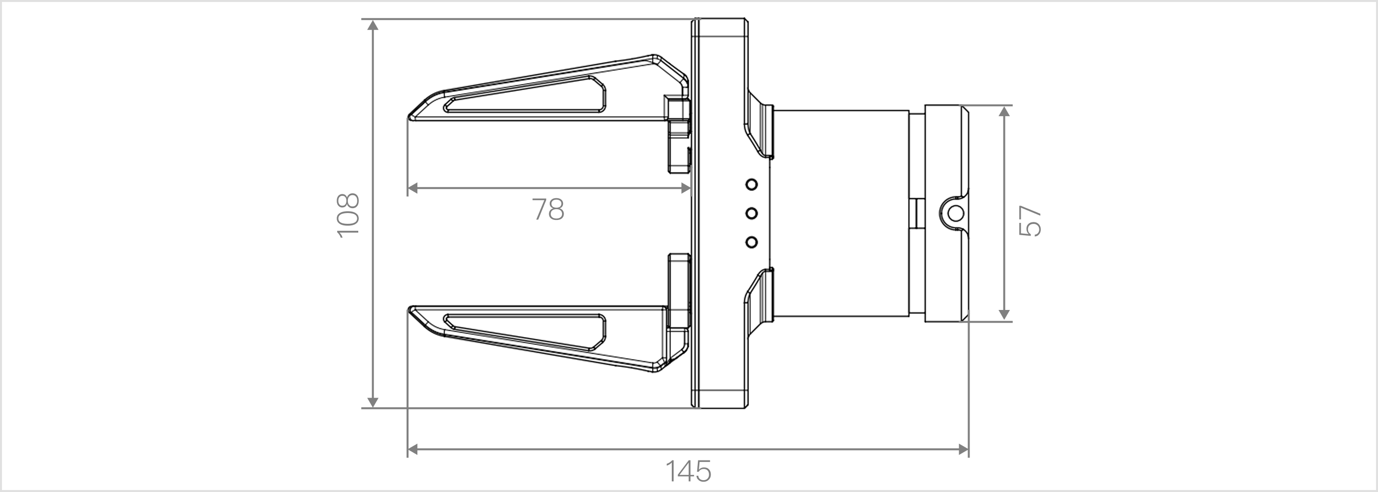
| Gripper | Remarks |
|---|---|
| Length | 145 mm |
| Finger Length | 78 mm |
| Motor Diameter | 57 mm |
| Gripper Operating Range | 0 ~ 100 mm |
| Gripper Rated Force | 100 N |
Installation
Follow the steps below to install the G1 gripper onto the end of the robotic arm (reverse the steps to remove the gripper).
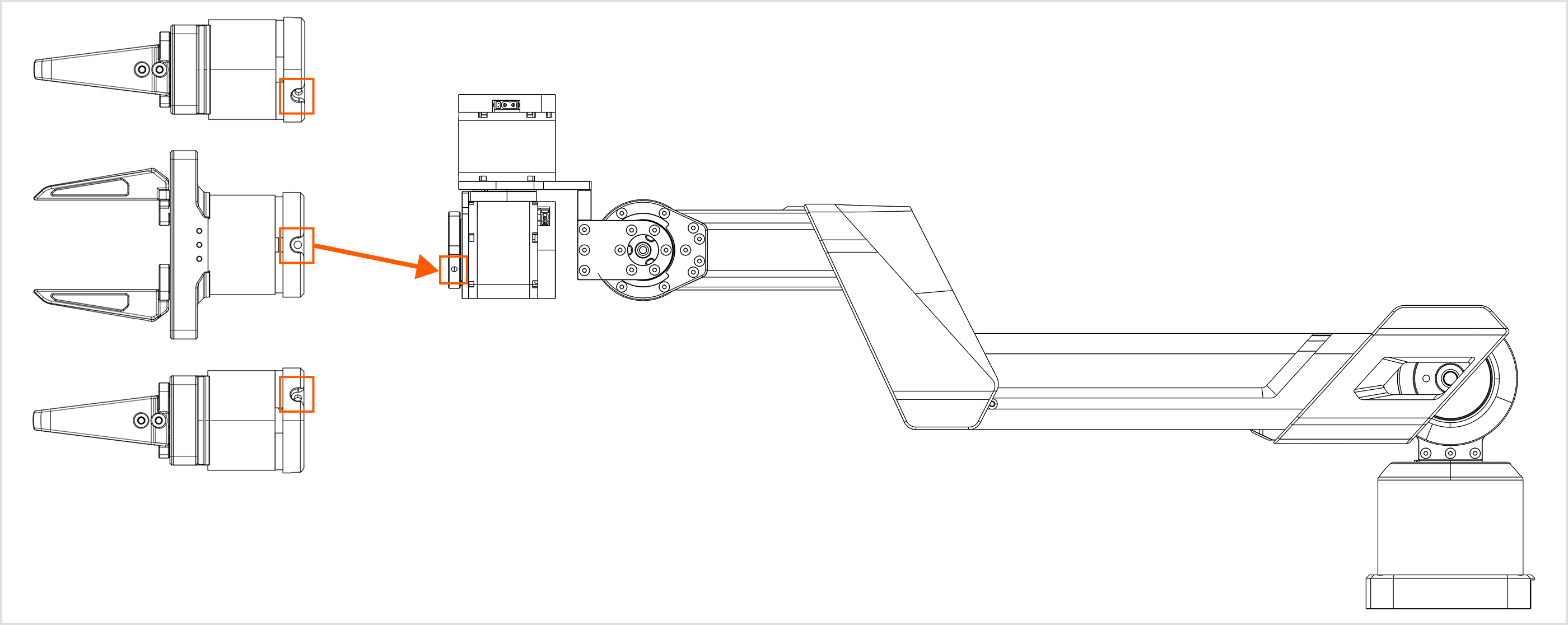
- Alignment check: Ensure the 3 mounting holes around the gripper are aligned with the 3 mounting holes at the end of the robotic arm.
- Screw fixing: After alignment, use the 3 provided screws to fix and tighten the gripper onto the end of the robotic arm.
- Security check: After tightening the screws, check again whether the gripper is properly aligned and securely mounted.
- Connect the harness: Connect the CAN harness on the outer side of J6 at the end of the robotic arm to the communication port of the gripper.
Installing Other End-Effectors
Follow the steps below to install other end-effectors onto the end of the robotic arm (reverse the steps to remove them). A dexterous hand is used here as an example.
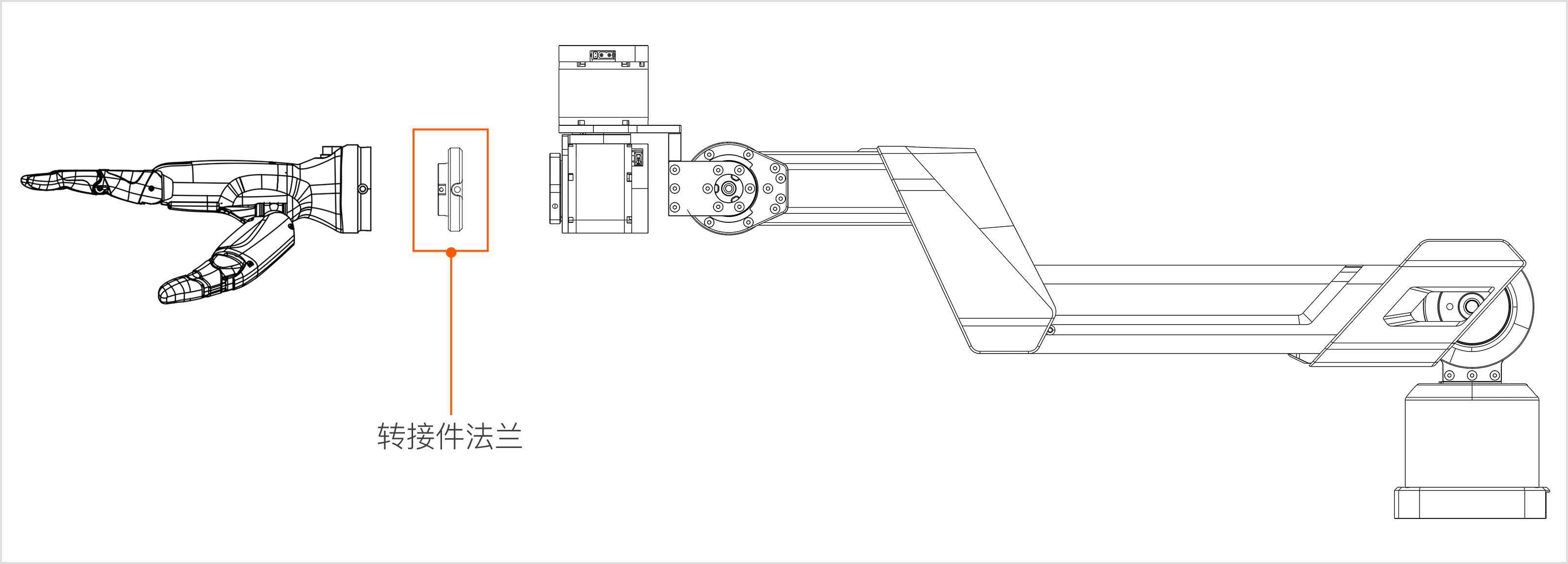
- Alignment check: Using the custom adapter flange, align the 4 mounting holes around the flange with the dexterous hand, and align the flange with the 3 mounting holes around the end of the robotic arm.
- Screw fixing: After alignment, use the provided screws to fix and connect the dexterous hand, flange, and the end of the robotic arm together.
- Security check: After tightening the screws, check again whether the dexterous hand is properly aligned and securely mounted.
- Connect the harness: Connect the CAN harness on the outer side of joint J6 at the end of the robotic arm to the communication port of the end-effector.
The flange STP file can be found athttps://github.com/userguide-galaxea/STP/tree/main/A1X