Motion Control Interface
- Arm Joint Control: This node controls each joint of the arm.
- Arm Pose Control: This node controls the arm to move to the target end-effector (ee) coordinate frame, split into pose control for the left arm and pose control for the right arm.
- Gripper Control: This node controls the opening and closing of the gripper.
- Torso Velocity Control: This node controls the torso to move to the target floating base coordinate frame.
- Torso Joint Control: This node controls the motion of individual torso joints.
- Chassis Control: This node uses vector control to drive the Galaxea R1 Lite chassis, allowing velocity commands in the x, y, and w directions to be sent simultaneously.
Arm Joint Control
The arm joint control node controls each joint of the arm, with a total of 6 joints.
It can be launched with the following command:
# Before calling the following interfaces, please confirm that FDCAN communication and the HDAS node are started (refer to the Separate Startup section for the procedure)
# Choose one of the following two launches to start; essentially they differ in the joint velocity limit parameters
ros2 launch mobiman r1_lite_jointTrackerdemo_launch.py                #(Normal Mode)
ros2 launch mobiman r1_lite_jointTrackerdemo_fast_launch.py           #(High-Follow Mode)
The interface information is as follows:
| Topic Name | I/O | Description | Message Type |
|---|---|---|---|
| /motion_target/target_joint_state_arm_left | Input | Target position of each left arm joint | sensor_msgs::msg::JointState |
| /motion_target/target_joint_state_arm_right | Input | Target position of each right arm joint | sensor_msgs::msg::JointState |
| /hdas/feedback_arm_left | Input | Left arm joint feedback | sensor_msgs::msg::JointState |
| /hdas/feedback_arm_right | Input | Right arm joint feedback | sensor_msgs::msg::JointState |
| /motion_control/control_arm_left | Output | Left arm motor control | hdas_msg::msg::MotorControl |
| /motion_control/control_arm_right | Output | Right arm motor control | hdas_msg::msg::MotorControl |
The specific fields of the topics above and their detailed descriptions are shown in the following table:
| Topic Name | Field | Description |
|---|---|---|
| /motion_target/target_joint_state_arm_left /motion_target/target_joint_state_arm_right |
header | Standard message header |
| position | A vector of six elements representing the six target positions of each joint. | |
| velocity | A vector of six elements representing the maximum velocity of each joint during motion. | |
| /hdas/feedback_arm_left | - | Please refer to the arm driver interface |
| /hdas/feedback_arm_right | - | Please refer to the arm driver interface |
| /motion_control/control_arm_left | - | Please refer to the arm driver interface |
| /motion_control/control_arm_right | - | Please refer to the arm driver interface |
Arm Pose Control
Arm pose control is a ROS package used to control the arm to move to the target end-effector (ee) coordinate frame. It mainly includes two launch files, corresponding to pose control for the left arm and pose control for the right arm respectively.
It can be launched with the following command:
# Before calling the following interfaces, please confirm that FDCAN communication, the HDAS node, and the arm joint control node are started;
# For the startup of FDCAN communication and the HDAS node, refer to the Separate Startup section; for the startup of the arm joint control node, refer to the Arm Joint Control section;
ros2 launch mobiman r1_lite_left_arm_relaxed_ik_launch.py
# Then open a new terminal
ros2 launch mobiman r1_lite_right_arm_relaxed_ik_launch.py
# Input: target pose to be solved
/motion_target/target_pose_arm_left
/motion_target/target_pose_arm_right
# Output: solved target joint angles
/motion_target/target_joint_state_arm_left
/motion_target/target_joint_state_arm_right
Note: Since pose control continuously solves the target joint angles from the target pose, the joint angle control node must be started in advance:
source {sdk_path}/install/setup.bash
ros2 launch mobiman r1_lite_jointTrackerdemo_launch.py
Use the following command to start the arm pose feedback node:
source install setup.bash
ros2 launch mobiman r1_lite_eepose_launch.py
The interface information is as follows:
| Topic Name | I/O | Description | Message Type |
|---|---|---|---|
| /hdas/feedback_arm_left | Input | Left arm joint feedback | sensor_msgs::msg::JointState |
| /hdas/feedback_arm_right | Input | Right arm joint feedback | sensor_msgs::msg::JointState |
| /motion_target/target_pose_arm_left | Input | Target left arm end-effector pose | geometry_msgs::msg::PoseStamped |
| /motion_target/target_pose_arm_right | Input | Target right arm end-effector pose | geometry_msgs::msg::PoseStamped |
| /motion_target/target_joint_state_arm_left | Output | Left arm joint target position | sensor_msgs::msg::JointState |
| /motion_target/target_joint_state_arm_right | Output | Right arm joint target position | sensor_msgs::msg::JointState |
| /motion_control/pose_ee_arm_left | Output | Actual left arm end-effector pose | geometry_msgs::msg::PoseStamped |
| /motion_control/pose_ee_arm_right | Output | Actual right arm end-effector pose | geometry_msgs::msg::PoseStamped |
The specific fields of the topics above and their detailed descriptions are shown in the following table:
| Topic Name | Field | Description |
|---|---|---|
| /hdas/feedback_arm_left /hdas/feedback_arm_right |
- | Please refer to the arm driver interface |
| /motion_target/target_pose_arm_left /motion_target/target_pose_arm_right |
header | Standard message header |
| pose.position.x | X-axis offset | |
| pose.position.y | Y-axis offset | |
| pose.position.z | Z-axis offset | |
| pose.orientation.x | Rotation quaternion | |
| pose.orientation.y | Rotation quaternion | |
| pose.orientation.z | Rotation quaternion | |
| pose.orientation.w | Rotation quaternion | |
| /motion_target/target_joint_state_arm_left /motion_target/target_joint_state_arm_right |
- | Please refer to the joint control interface |
| /motion_control/pose_ee_arm_left /motion_control/pose_ee_arm_right |
header | Standard message header |
| pose.position.x | X-axis offset | |
| pose.position.y | Y-axis offset | |
| pose.position.z | Z-axis offset | |
| pose.orientation.x | Rotation quaternion | |
| pose.orientation.y | Rotation quaternion | |
| pose.orientation.z | Rotation quaternion | |
| pose.orientation.w | Rotation quaternion |
Gripper Control
It can be launched with the following command:
# Before calling the following interfaces, please confirm that FDCAN communication and the HDAS node are started (refer to the Separate Startup section for the procedure)
ros2 launch mobiman r1_gripperController_launch.py robot_type:=R1LITE
Note: This launch file starts the R1_Gripper_Controller, not the R1_Pro_Gripper_Controller here.
The interface information is as follows:
| Topic Name | I/O | Description | Message Type |
|---|---|---|---|
| /motion_target/target_position_gripper_left | Input | Left gripper target position | sensor_msgs::msg::JointState |
| /motion_target/target_position_gripper_right | Input | Right gripper target position | sensor_msgs::msg::JointState |
| /motion_control/control_gripper_left | Output | Left gripper motor control | hdas_msg::msg::MotorControl |
| /motion_control/control_gripper_right | Output | Right gripper motor control | hdas_msg::msg::MotorControl |
The specific fields of the topics above and their detailed descriptions are shown in the following table:
| Topic Name | Field | Description |
|---|---|---|
| /motion_target/target_position_gripper_left /motion_target/target_position_gripper_right |
position | Represents the target position of the left and right grippers [0, 100], 0 means fully closed, 100 means fully open. |
| /motion_control/control_gripper_left /motion_control/control_gripper_right |
- | Please refer to the arm driver interface |
Torso Velocity Control
Torso velocity control is a ROS package used to control the torso to move to the target floating base coordinate frame.
It can be launched with the following command:
# Before calling the following interfaces, please confirm that FDCAN communication and the HDAS node are started (refer to the Separate Startup section for the procedure)
ros2 launch mobiman torso_control_r1_lite.launch.py
The interface information is as follows:
| Topic Name | I/O | Description | Message Type |
|---|---|---|---|
| /motion_target/target_speed_torso | Input | Target velocity of the floating base frame | geometry_msgs::msg::TwistStamped |
| /hdas/feedback_torso | Input | Torso joint feedback | sensor_msgs::msg::JointState |
| /motion_control/control_torso (this interface cannot actively publish messages) | Output | Torso joint control | hdas_msg::msg::MotorControl |
The specific fields of the topics above and their detailed descriptions are shown in the following table:
| Topic Name | Field | Description |
|---|---|---|
| /motion_target/target_speed_torso | target_speed.v_x = msg->linear.x | Linear velocity of the torso in the x direction in Cartesian space, [-0.2,0.2]m/s; -0.1≤x≤0.2 |
| target_speed.v_z = msg->linear.z | Linear velocity of the torso in the z direction in Cartesian space, [-0.2,0.2]m/s; 0.1≤z≤0.7 |
|
| target_speed.v_pitch = msg->twist.angular.y | Pitch angular velocity of the torso in Cartesian space | |
| target_speed.v_yaw = msg->twist.angular.z | Yaw angular velocity of the torso in Cartesian space | |
| /hdas/feedback_torso | - | Please refer to the torso driver interface |
| /motion_control/control_torso (this interface cannot actively publish messages) | - | Please refer to the torso driver interface |
As shown in the figure, this control node represents the velocity control of torsolink3 relative to base_link, with the same direction as the base_link frame.
`
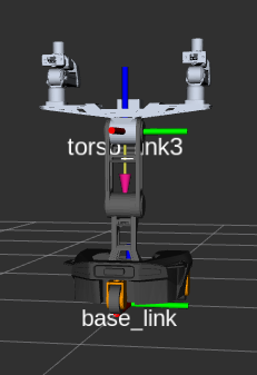
- v_x is the velocity of the torso frame in the x direction relative to
base_link(maximum velocity is 0.1m/s); a positive value means forward relative tobase_link, a negative value means backward; - v_z is the velocity of the torso frame in the z direction relative to
base_link(maximum velocity is 0.1m/s); a positive value means upward relative tobase_link, a negative value means downward; - w_pitch is the angular velocity of the torso frame in the y direction relative to
base_link(maximum velocity is 0.3rad/s); the direction follows the right-hand coordinate system; - w_yaw is the angular velocity of the torso frame in the z direction relative to
base_link(maximum velocity is 0.3rad/s); the direction follows the right-hand coordinate system.
Torso Joint Control
The torso joint control node controls each joint of the torso, with a total of 3 joints.
It can be launched with the following command:
source {your_download_path}/install/setup.bash
source /opt/galaxea/galaxeaKey/keys.env
# Choose one of the following two launches to start
# The difference between High-Follow and Normal modes is mainly the difference in the maximum joint velocity limit of the arms; the torso follow velocity is the same
# Before calling the following interfaces, please confirm that FDCAN communication and the HDAS node are started (refer to the Separate Startup section for the procedure)
ros2 launch mobiman r1_lite_jointTrackerdemo_fast_launch.py disable_torso:=false          #(High-Follow Mode)(default)
ros2 launch mobiman r1_lite_jointTrackerdemo_launch.py disable_torso:=false               #(Normal Mode)
Note: The torso joint control node and the arm control node are the same node
Special note: Although the torso velocity control node and the joint control node can be started together, the torso velocity control signal and the torso joint control signal cannot be mixed, otherwise it will cause joint conflicts and danger
# That is, the following two topics cannot be mixed when the torso velocity control node and the joint control node are started together; only one of the two can be chosen, otherwise it will cause joint conflicts and danger
/motion_target/target_speed_torso
/motion_target/target_joint_state_torso
It is worth noting that in the startup method above, the disable_torso parameter is set to false. Then, through the key pairing stored in /opt/galaxea/galaxeaKey/keys.env, torso joint control can be achieved.
The interface information is as follows:
| Topic Name | I/O | Description | Message Type |
|---|---|---|---|
| /motion_target/target_joint_state_torso | Input | Target position of each torso joint | sensor_msgs::msg::JointState |
| /hdas/feedback_torso | Input | Torso joint feedback | sensor_msgs::msg::JointState |
The specific fields of the topics above and their detailed descriptions are shown in the following table:
| Message Name | Field | Description |
|---|---|---|
| /motion_target/target_joint_state_torso | header | Standard message header |
| position | A vector of 3 elements representing the target position of each joint. | |
| velocity | A vector of 3 elements representing the maximum velocity of each joint during motion. | |
| /hdas/feedback_torso | - | Please refer to the arm driver interface |
Chassis Control
Chassis control is a node that uses vector control to drive the Galaxea R1 Lite chassis, allowing velocity commands in the x, y, and w directions to be sent simultaneously.
It can be launched with the following command:
# Before calling the following interfaces, please confirm that FDCAN communication and the HDAS node are started (refer to the Separate Startup section for the procedure)
ros2 launch mobiman r1_lite_chassis_control_w_o_eepose_launch.py
This file starts a node: r1_lite_chassis_control_node, which is responsible for the velocity control of the Galaxea R1 Lite chassis. Its interface is as follows:
| Topic Name | I/O | Description | Message Type |
|---|---|---|---|
| /motion_target/target_speed_chassis | Input | Target velocity of the chassis, including vx, vy and omega | geometry_msgs::msg::TwistStamped |
| /motion_target/chassis_acc_limit | Input | Acceleration limits of the chassis, with maximum values of 2.5, 1.0, 1.0 respectively | geometry_msgs::msg::TwistStamped |
| /motion_target/brake_mode | Input | Issues a command on whether the chassis enters brake mode. If in brake mode, when the velocity is 0, the chassis will lock itself by turning the wheels a certain angle. |
std_msgs::msg::Bool |
| /hdas/feedback_chassis | Input | The Galaxea R1 Lite chassis control subscribes to this topic and controls the target velocity of the chassis. | sensor_msgs::msg::JointState |
| /motion_control/control_chassis | Output | The Galaxea R1 Lite chassis control publishes this topic to control the motors. | hdas_msg::msg::MotorControl |
The specific fields of the topics above and their detailed descriptions are shown in the following table:
| Message Name | Field | Description |
|---|---|---|
| /motion_target/target_speed_chassis | header | Standard message header |
| linear | Linear velocity | |
| .x | Linear velocity x, range (-1.5, 1.5) m/s | |
| .y | Linear velocity y, range (-1.5, 1.5) m/s | |
| angular | Angular velocity | |
| .z | Angular velocity, range (-3, - 3) rad/s | |
| /motion_target/chassis_acc_limit | header | Standard message header |
| linear | Linear velocity | |
| .x | Acceleration limit x, range (-2.5, 2.5) m/s² | |
| .y | Acceleration limit y, range (-1.0, 1.0) m/s² | |
| angular | Angular velocity | |
| .z | Angular velocity limit, range (-3, 3) rad/s² | |
| /motion_target/brake_mode | data | Boolean value Enter brake mode: True Exit brake mode: False |
| /hdas/feedback_chassis | - | Please refer to the chassis driver interface |
| /motion_control/control_chassis | - | Please refer to the chassis driver interface |